Grove : Capteur d'électricité
De Wikidebrouillard.
| Ligne 1 : | Ligne 1 : | ||
| - | == Introduction | + | == Introduction == |
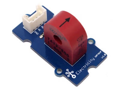
| - | + | Le capteur d’électricité fait partie des modules Grove. Il fonctionne à partir d'un transformateur de courant TA12-200 qui convertit le courant alternatif en courant de plus faible amplitude. Il permet de tester d'importants courants électriques alternatifs, jusqu'à 5 A. | |
| - | + | Modèle :[http://www.seeedstudio.com/depot/grove-electricity-sensor-p-777.html?cPath=144_154 SEN23931P] | |
| - | [[Image:Twig-Electricity-Sensor.jpg|400px|Twig | + | [[Image:Twig-Electricity-Sensor.jpg|400px|Capteur d'électricité Twig.jpg]] |
| - | == | + | == Caractéristiques == |
| - | * | + | *Interface compatible Grove |
| - | * | + | *Alimentation maximale: 5 A |
| - | * | + | *Haute précision |
| - | * | + | *Taille réduite |
| - | == | + | == Suggestions d'utilisation == |
| - | * | + | *Mesure du courant alternatif |
| - | * | + | *Contrôle de l'état d'un appareil |
| - | == | + | == Caractéristiques techniques == |
| - | == | + | == Principales caractéristiques techniques == |
{| border="1" class="wikitable" | {| border="1" class="wikitable" | ||
|- | |- | ||
| - | | width="400" align="center" | ''' | + | | width="400" align="center" | '''Éléments''' |
| width="400" align="center" | '''Min''' | | width="400" align="center" | '''Min''' | ||
|- style="font-size: 90%" | |- style="font-size: 90%" | ||
| - | | align="center" | PCB | + | | align="center" | Taille du PCB |
| - | | align="center" | 2 | + | | align="center" | 2,0 cm x 4,0 cm |
|- style="font-size: 90%" | |- style="font-size: 90%" | ||
| align="center" | Interface | | align="center" | Interface | ||
| - | | align="center" | 2 | + | | align="center" | Écartement des broches 2,0 mm |
|- style="font-size: 90%" | |- style="font-size: 90%" | ||
| - | | align="center" | | + | | align="center" | Structure I/O (entrée/sortie) |
| align="center" | SIG,NC,NC,GND | | align="center" | SIG,NC,NC,GND | ||
|- style="font-size: 90%" | |- style="font-size: 90%" | ||
| align="center" | ROHS | | align="center" | ROHS | ||
| - | | align="center" | | + | | align="center" | OUI |
|} | |} | ||
| - | === | + | === Caractéristiques électroniques === |
| - | {| | + | {| class="wikitable" border="1" |
|- | |- | ||
| - | | width="300" align="center" | ''' | + | | width="300" align="center" | '''Éléments''' |
| width="100" align="center" | '''Min''' | | width="100" align="center" | '''Min''' | ||
| - | | width="100" align="center" | ''' | + | | width="100" align="center" | '''Normal''' |
| - | | width="100" align="center" | '''Max''' | + | | width="100" align="center" | '''Max.''' |
| - | | width="100" align="center" | ''' | + | | width="100" align="center" | '''Unité''' |
|- | |- | ||
| - | | align="center" | | + | | align="center" | Rapport de transformation |
| align="center" | - | | align="center" | - | ||
| align="center" | 2000:1 | | align="center" | 2000:1 | ||
| Ligne 57 : | Ligne 57 : | ||
| align="center" | - | | align="center" | - | ||
|- | |- | ||
| - | | align="center" | | + | | align="center" | Courant d'entrée |
| align="center" | 0 | | align="center" | 0 | ||
| align="center" | - | | align="center" | - | ||
| Ligne 63 : | Ligne 63 : | ||
| align="center" | A | | align="center" | A | ||
|- | |- | ||
| - | | align="center" | | + | | align="center" | Courant de sortie |
| align="center" | 0 | | align="center" | 0 | ||
| align="center" | - | | align="center" | - | ||
| - | | align="center" | 2 | + | | align="center" | 2,5 |
| align="center" | mA | | align="center" | mA | ||
|- | |- | ||
| - | | align="center" | | + | | align="center" | Résistance d'échantillonnage |
| align="center" | - | | align="center" | - | ||
| align="center" | 800 | | align="center" | 800 | ||
| Ligne 75 : | Ligne 75 : | ||
| align="center" | Ω | | align="center" | Ω | ||
|- | |- | ||
| - | | align="center" | | + | | align="center" | Tension d’échantillonnage |
| align="center" | 0 | | align="center" | 0 | ||
| align="center" | - | | align="center" | - | ||
| Ligne 81 : | Ligne 81 : | ||
| align="center" | V | | align="center" | V | ||
|- | |- | ||
| - | | align="center" | | + | | align="center" | Fréquence de travail |
| align="center" | 20 | | align="center" | 20 | ||
| align="center" | - | | align="center" | - | ||
| - | | align="center" | | + | | align="center" | 20 K |
| align="center" | HZ | | align="center" | HZ | ||
|- | |- | ||
| - | | align="center" | | + | | align="center" | Échelle non-linéaire |
| align="center" | - | | align="center" | - | ||
| align="center" | - | | align="center" | - | ||
| - | | align="center" | 0 | + | | align="center" | 0,2 % |
| align="center" | - | | align="center" | - | ||
|- | |- | ||
| - | | align="center" | | + | | align="center" | Déphasage |
| align="center" | - | | align="center" | - | ||
| align="center" | - | | align="center" | - | ||
| Ligne 99 : | Ligne 99 : | ||
| align="center" | - | | align="center" | - | ||
|- | |- | ||
| - | | align="center" | | + | | align="center" | Température de fonctionnement |
| align="center" | -55 | | align="center" | -55 | ||
| align="center" | - | | align="center" | - | ||
| Ligne 105 : | Ligne 105 : | ||
| align="center" | ℃ | | align="center" | ℃ | ||
|- | |- | ||
| - | | align="center" | | + | | align="center" | Rigidité diélectrique |
| align="center" | - | | align="center" | - | ||
| align="center" | 6 | | align="center" | 6 | ||
| align="center" | - | | align="center" | - | ||
| - | | align="center" | KVAC/ | + | | align="center" | KVAC/1 min |
|} | |} | ||
| - | == | + | == Utilisation == |
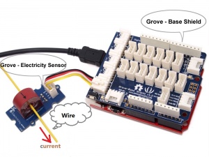
| - | + | Le schéma qui suit illustre l'utilisation de la mesure d'amplitude d'un courant alternatif. La broche SIG délivre une tension alternative basée sur le courant alternatif mesuré. Il est possible de mesurer la valeur en utilisant un convertisseur A/N (analogique-numérique). | |
| - | * | + | *Connecter le module à l'entrée analogue A0 de [http://www.seeedstudio.com/depot/grove-base-shield-p-754.html?cPath=132_134 Grove - Base board] |
| - | * | + | *Mettre le fil du courant alternatif dans le trou du transformateur de courant. |
| - | [[Image:Grove - Electricity Sensor hardware.jpg|300px]]<br> | + | [[Image:Grove - Electricity Sensor hardware.jpg|300px|Image:Capteur d'électricité Grove.jpg]]<br> |
| - | * | + | *Copier et coller le code ci-dessous dans un nouveau programme Arduino. <br> |
<pre> | <pre> | ||
/****************************************************************************/ | /****************************************************************************/ | ||
| - | // | + | // Fonction : mesure l'amplitude du courant alternatif et |
| - | // | + | // la valeur effective du courant alternatif sinusoïdal. |
| - | // | + | // matériel : capteur d'électricité Grove |
| - | // Date: | + | // Date: 19 jan. 2013 |
| - | // | + | // par www.seeedstudio.com |
| - | #define ELECTRICITY_SENSOR A0 // | + | #define ELECTRICITY_SENSOR A0 // La broche d'entrée analogique à laquelle le capteur est raccordé |
| - | float amplitude_current; //amplitude | + | float amplitude_current; // amplitude du courant |
| - | float effective_value; // | + | float effective_value; // courant effectif |
void setup() | void setup() | ||
| Ligne 143 : | Ligne 143 : | ||
Serial.print("sensor_max = "); | Serial.print("sensor_max = "); | ||
Serial.println(sensor_max); | Serial.println(sensor_max); | ||
| - | // | + | //La valeur de la Vcc sur l'interface Grove du capteur est de 5 V. |
amplitude_current=(float)sensor_max/1024*5/800*2000000; | amplitude_current=(float)sensor_max/1024*5/800*2000000; | ||
effective_value=amplitude_current/1.414;//minimum_current=1/1024*5/800*2000000/1.414=8.6(mA) | effective_value=amplitude_current/1.414;//minimum_current=1/1024*5/800*2000000/1.414=8.6(mA) | ||
| - | // | + | // Uniquement pour le courant alternatif sinusoïdal |
Serial.println("The amplitude of the current is(in mA)"); | Serial.println("The amplitude of the current is(in mA)"); | ||
| - | Serial.println(amplitude_current,1);// | + | Serial.println(amplitude_current,1);// Seulement un chiffre après la virgule |
Serial.println("The effective value of the current is(in mA)"); | Serial.println("The effective value of the current is(in mA)"); | ||
Serial.println(effective_value,1); | Serial.println(effective_value,1); | ||
| Ligne 156 : | Ligne 156 : | ||
pinMode(ELECTRICITY_SENSOR, INPUT); | pinMode(ELECTRICITY_SENSOR, INPUT); | ||
} | } | ||
| - | /* | + | /*Fonction : échantillonne sur 1000 ms et obtient la valeur maximale de la broche SIG*/ |
int getMaxValue() | int getMaxValue() | ||
{ | { | ||
| - | int sensorValue; // | + | int sensorValue; // valeur restituée par le capteur |
int sensorMax = 0; | int sensorMax = 0; | ||
uint32_t start_time = millis(); | uint32_t start_time = millis(); | ||
| Ligne 167 : | Ligne 167 : | ||
if (sensorValue > sensorMax) | if (sensorValue > sensorMax) | ||
{ | { | ||
| - | /* | + | /*enregistre la valeur maximale du capteur*/ |
sensorMax = sensorValue; | sensorMax = sensorValue; | ||
} | } | ||
| Ligne 174 : | Ligne 174 : | ||
} | } | ||
</pre> | </pre> | ||
| - | * | + | *Télécharger le code. Si vous ne savez pas comment faire, cliquez [http://www.seeedstudio.com/wiki/Upload_Code ici].<br> |
| - | ''' | + | '''Remarque :''' le courant effectif minimum capté par le code peut être calculé en utilisant l'équation suivante. |
minimum_current=1/1024*5/800*2000000/1.414=8.6(mA).<br> | minimum_current=1/1024*5/800*2000000/1.414=8.6(mA).<br> | ||
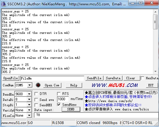
| - | * | + | *Ouvrir le moniteur série pour voir le résultat :<br> |
| - | [[Image:Elecricity_Sensor.jpg]] | + | [[Image:Elecricity_Sensor.jpg|Capteur d'électricité.jpg]] |
| - | == | + | == Ressources == |
*[http://www.seeedstudio.com/wiki/File:Electricity_sensor_v1.0_eagle_files.zip Grove -Electricity Sensor Eagle File] | *[http://www.seeedstudio.com/wiki/File:Electricity_sensor_v1.0_eagle_files.zip Grove -Electricity Sensor Eagle File] | ||
*[http://www.seeedstudio.com/wiki/File:Electricity_sensor_sch.pdf Schematic in PDF] | *[http://www.seeedstudio.com/wiki/File:Electricity_sensor_sch.pdf Schematic in PDF] | ||
| - | == | + | == Aller plus loin == |
| - | + | Si vous avez des questions ou des suggestions d'amélioration rendez-vous sur notre [http://www.seeedstudio.com/forum forum], ou sur notre plateforme [http://wish.seeedstudio.com wish] pour nous en faire part. | |
==Crédits== | ==Crédits== | ||
Cette page est la traduction de celle-ci : http://www.seeedstudio.com/wiki/index.php?title=Twig_-_Electricity_Sensor | Cette page est la traduction de celle-ci : http://www.seeedstudio.com/wiki/index.php?title=Twig_-_Electricity_Sensor | ||
| - | Traducteurs : | + | Traducteurs : Adèle Boulo et Salomé Moreau - 2013 dans le cadre de [[Master 2 rédacteur traducteur 2013]] |
[[Catégorie:arduino]] | [[Catégorie:arduino]] | ||
Version du 19 décembre 2013 à 15:10
Sommaire |
Introduction
Le capteur d’électricité fait partie des modules Grove. Il fonctionne à partir d'un transformateur de courant TA12-200 qui convertit le courant alternatif en courant de plus faible amplitude. Il permet de tester d'importants courants électriques alternatifs, jusqu'à 5 A.
Modèle :SEN23931P
Caractéristiques
- Interface compatible Grove
- Alimentation maximale: 5 A
- Haute précision
- Taille réduite
Suggestions d'utilisation
- Mesure du courant alternatif
- Contrôle de l'état d'un appareil
Caractéristiques techniques
Principales caractéristiques techniques
| Éléments | Min |
| Taille du PCB | 2,0 cm x 4,0 cm |
| Interface | Écartement des broches 2,0 mm |
| Structure I/O (entrée/sortie) | SIG,NC,NC,GND |
| ROHS | OUI |
Caractéristiques électroniques
| Éléments | Min | Normal | Max. | Unité |
| Rapport de transformation | - | 2000:1 | - | - |
| Courant d'entrée | 0 | - | 5 | A |
| Courant de sortie | 0 | - | 2,5 | mA |
| Résistance d'échantillonnage | - | 800 | - | Ω |
| Tension d’échantillonnage | 0 | - | 2 | V |
| Fréquence de travail | 20 | - | 20 K | HZ |
| Échelle non-linéaire | - | - | 0,2 % | - |
| Déphasage | - | - | 5' | - |
| Température de fonctionnement | -55 | - | 85 | ℃ |
| Rigidité diélectrique | - | 6 | - | KVAC/1 min |
Utilisation
Le schéma qui suit illustre l'utilisation de la mesure d'amplitude d'un courant alternatif. La broche SIG délivre une tension alternative basée sur le courant alternatif mesuré. Il est possible de mesurer la valeur en utilisant un convertisseur A/N (analogique-numérique).
- Connecter le module à l'entrée analogue A0 de Grove - Base board
- Mettre le fil du courant alternatif dans le trou du transformateur de courant.
- Copier et coller le code ci-dessous dans un nouveau programme Arduino.
/****************************************************************************/
//	Fonction : mesure l'amplitude du courant alternatif et
//			 la valeur effective du courant alternatif sinusoïdal.
//	matériel : capteur d'électricité Grove
//	Date: 	 19 jan. 2013
//	par www.seeedstudio.com
#define ELECTRICITY_SENSOR A0 // La broche d'entrée analogique à laquelle le capteur est raccordé

float amplitude_current;               // amplitude du courant
float effective_value;       // courant effectif

void setup()
{
	Serial.begin(9600);
	pins_init();
}
void loop()
{
	int sensor_max;
	sensor_max = getMaxValue();
	Serial.print("sensor_max = ");
	Serial.println(sensor_max);
	//La valeur de la Vcc sur l'interface Grove du capteur est de 5 V.
	amplitude_current=(float)sensor_max/1024*5/800*2000000;
	effective_value=amplitude_current/1.414;//minimum_current=1/1024*5/800*2000000/1.414=8.6(mA)
						// Uniquement pour le courant alternatif sinusoïdal
	Serial.println("The amplitude of the current is(in mA)");
	Serial.println(amplitude_current,1);// Seulement un chiffre après la virgule
	Serial.println("The effective value of the current is(in mA)");
	Serial.println(effective_value,1);
}
void pins_init()
{
	pinMode(ELECTRICITY_SENSOR, INPUT);
}
/*Fonction : échantillonne sur 1000 ms et obtient la valeur maximale de la broche SIG*/
int getMaxValue()
{
	int sensorValue;             // valeur restituée par le capteur
	int sensorMax = 0;
	uint32_t start_time = millis();
	while((millis()-start_time) < 1000)//sample for 1000ms
	{
		sensorValue = analogRead(ELECTRICITY_SENSOR);
		if (sensorValue > sensorMax)
		{
			/*enregistre la valeur maximale du capteur*/
			sensorMax = sensorValue;
		}
	}
	return sensorMax;
}
- Télécharger le code. Si vous ne savez pas comment faire, cliquez ici.
Remarque : le courant effectif minimum capté par le code peut être calculé en utilisant l'équation suivante.
minimum_current=1/1024*5/800*2000000/1.414=8.6(mA).
- Ouvrir le moniteur série pour voir le résultat :
Ressources
Aller plus loin
Si vous avez des questions ou des suggestions d'amélioration rendez-vous sur notre forum, ou sur notre plateforme wish pour nous en faire part.
Crédits
Cette page est la traduction de celle-ci : http://www.seeedstudio.com/wiki/index.php?title=Twig_-_Electricity_Sensor
Traducteurs : Adèle Boulo et Salomé Moreau - 2013 dans le cadre de Master 2 rédacteur traducteur 2013


